

Most tech-savvy gamers probably already know what PCI and PCI-e (PCI Express) are: “Yeah, it’s the slot the graphics card goes into, everyone knows that!” Yes, you’d be right about that, but there’s more to a PCI-e slot than meets the eye. It’s not just for GPUs; the PCI-e supports many different types of hardware. Let’s delve into the uses of PCI-e and discuss how PCI evolved into PCI Express.
Navigate to a section of interest:
What is PCI | How does PCI work | The Birth of PCI | PCIe Speeds
First, I’d like to touch base on what PCI is, to provide a little background history on how it came about and how it has evolved into PCIe (PCI Express). I’m not going to waffle on for hours on end: I’ll try to keep things simple and focus on the important bits. Hopefully this should give you a better understanding of the technology itself and its benefits.
PCI stands for ‘Peripheral Component Interconnect’. You can see why it was abbreviated. Now, let’s break that down a little further...
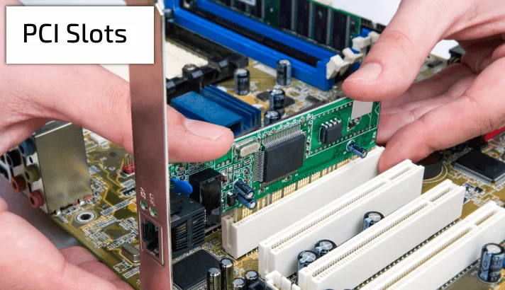
When your computer first boots up, the PCI checks the devices that are plugged in to the motherboard and identifies the link between each component, creating a traffic map and working out the width of each link. The newer PCIe does the same thing - I’ll talk more about that a little later on.
PCI is essentially a local computer bus… yes, a bus! Not the type that transfers passengers from A to B, but adequately named, as it serves a similar purpose. The computer bus attaches local hardware devices to a computer. The bus allows data to be passed back and forth, interconnecting internal devices to various components, just like a real bus transporting employees on their daily commute. The bus is the set of rules, or “protocol” that determines how data moves between devices. Just like a bus station, a computer will generally have several buses.
Each bus has a certain size, determined by its carrying capacity and speed, measured in megahertz (MHz). The faster the better! The bus speed itself usually refers to the Front Side Bus (FSB), which connects the computer’s CPU to the system memory and other internal components of the motherboard. Because of this, the FSB is also called the System Bus.
Work began on PCI 1.0 by Intel way back in 1990. PCI was first put to use in servers as the server expansion bus of choice, but to be perfectly honest the technology didn’t work too well. It wasn’t until late 1994, with PCI 2.0 and the 2nd gen Pentium PCs, when the ball really started rolling. By 1996, many manufacturers introduced PCI to their motherboards, primarily in computers using the Intel 486 microprocessor. The next big change was in 2004 with revision 2.3. This took the significant step of switching the PCI bus from the original 5.0 volt signaling to 3.3 volt signaling. Like revision 2.2, this upgrade supported the 5V and 3.3V keyed system board connectors, but the latest version supported only the 3.3V and Universal keyed add-in cards. Later revisions of PCI features continued until 2004, when it was finally superseded by PCI Express (PCIe).
PCI Express, PCIe or PCI-e, stands for ‘Peripheral Component Interconnect Express’ - another mouthful. The ‘express’ part was added, unsurprisingly, because of the new high-speed features it offered. PCIe is now a common interface on almost any new motherboard, supporting connections to expansion cards like graphics cards, sound cards, NVMe flash SSDs, ethernet cards and many other hardware components.

The outdated PCI interface uses shared parallel bus architecture, in which the PCI host and all devices share a common set of addresses, data and control lines, not ideal by today’s computer standards. PCI Express uses point-to-point topology, with separate serial links connecting every device to the root complex, or host. This leads to less chance for errors and far greater speeds, with no inherent limitation on concurrent access across multiple endpoints. PCI-e maintains backward compatibility with PCI.
Data is communicated to and from a PCIe slot, in so-called lanes. The number of lanes is called the lane-link width. A PCIe x1 slot only has 1 lane, so is limited in the amount of data it can transfer. To take up the bus metaphor again, this is similar to a road, where the amount of traffic flow is governed by its size. Even though we can’t increase a card’s speed, we could increase the amount of data sent to the card, by increasing the number of lanes and using a PCIe x4 slot. This is more like a motorway: more lanes allows for more traffic. In this case, the traffic, or data transfer rate is increased four times. Again, we can increase the amount of data to a PCIe card by switching to an x8 or x16 slot, doubling up the amount of lanes each time. This allows you to further increase the data throughput of the PCIe slot without having to increase the speed of its underlying electronics.

So, to summarize; The PCIe convention defines lane-link widths as one or more data-transmission lanes, connected serially. There are 1, 4, 8, 16 or 32 lanes in a single PCIe slot, denoted as x1, x2, x4, x8, x12, x16 and x32
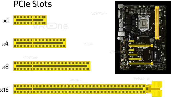
A larger PCIe bus can serve both cost-sensitive applications where high throughput is not needed, and performance-critical applications such as 3D graphics, gaming, networking etc. If you’re building your own computer, it’s worth giving where you place your cards in the PCIe some thought. Low-speed components, such as a Network Interface card (NIC), use a single-lane link. You could plug a single lane card, equivalent to a PCIe x1, into any slot, without issues. Just remember, the card's performance will remain the same in regards to the amount of data it receives and you’d just be wasting a high-speed x16 slot. Likewise, you could plug a PCIe x8 card into a PCIe x4 slot, but it would only have half the bandwidth available to it, as opposed to if it was plugged into an x8 slot.
Inevitably, all technology will improve over time, whether this is through innovation, or the pressures of consumer demand. The PCIe is no exception: it too has evolved to meet the demands of newer technologies. The earliest development being PCIe version 1.0 in 2004, right up to PCIe 5.0, formally released in May 2019. That being said, there are few computer technologies and hardware that support this latest edition. Currently, PCIe 4.0 is the latest supported version, being strongly established and available on several of the latest AMD motherboards, such as the Z490 chipset.
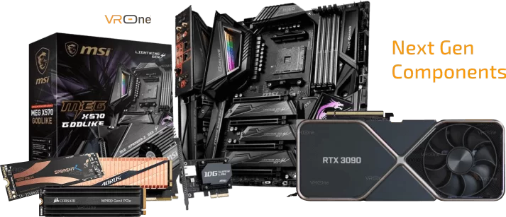
Amongst the components which take full advantage of the speeds offered by PCIe 4.0 are the new Gen4 NVMe M.2 SSDs, such as the Sabrent Rocket. The latest graphics cards, such as NVIDIA’s 3000 Series and AMDs BIG Navi are also PCIe 4.0 compliant, although there’s no real benefit there in regards to performance. Now, let’s take a look at the various speeds, or throughput, for the various versions of PCIe.
PCIe version 1.0 serves 250 Megabytes per second (MB/ps), per lane. This would be the maximum throughput for an x1 PCIe slot. As an x16 PCIe slot has 16 lanes, so theoretically has a maximum speed of 4 Gigabytes per second (GB/ps). The table below shows various top speeds depending on the version of PCIe being used.
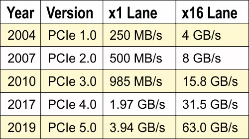
For further comparison on the various speeds offered by other lanes: x1, x4, x8 and x32, see the full version of the data chart - PCIe Speed Chart
All that being said, the actual speed and performance of a PCIe card is determined by the hardware generation itself. The PCIe will operate at the lowest data transfer rate between the two main components. For example: If a motherboard is PCIe 3.0 compliant and you plug a PCIe 2.0 card into the motherboard, the card will run at the speed of the older version.
That’s it on PCI and PCI Express. If you're interested in finding out more, check out our next article on PCIe 4.0 supported cards, where I’ll be discussing the benefits it offers and which compatible components support it.
If you have any questions, or want to add a comment to this article, please add them to the box below.



What is PCI and PCIe